Projects Of Engineering


Engineering is the science, discipline, art and profession of acquiring and applying technical, scientific and mathematical knowledge to design and implement materials, structures, machines, devices, systems, and processes that safely realize a desired objective or inventions.
The American Engineers' Council for Professional Development (ECPD, the predecessor of ABET) has defined engineering as follows:
“[T]he creative application of scientific principles to design or develop structures, machines, apparatus, or manufacturing processes, or works utilizing them singly or in combination; or to construct or operate the same with full cognizance of their design; or to forecast their behavior under specific operating conditions; all as respects an intended function, economics of operation and safety to life and property.”


One who practices engineering is called an engineer, and those licensed to do so may have more formal designations such as Professional Engineer, Chartered Engineer, Incorporated Engineer, or European Engineer. The broad discipline of engineering encompasses a range of more specialized subdisciplines, each with a more specific emphasis on certain fields of application and particular areas of technology.




Random Flasher for 8 LEDs Project


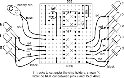
This project flashes eight LEDs in an apparently random manner. It uses a 4026 combined counter and display driver IC which is designed for driving 7-segment LED displays. The sequence is not really random because seven of the LEDs would normally be the display segments, the eighth LED is driven by an output that is normally used for driving further counters. The table below shows the sequence for the LEDs. You can use less than eight LEDs if you wish and the table may help you decide which ones to use for your purpose.

This project uses a 555 astable circuit to provide the clock pulses for the 4026 counter.


Resistors are not required for the LEDs because the 4026 IC limits the current to about 5mA for each LED.


Download PDF version of this page


Parts Required

resistors: 10k, 47k
capacitor: 1µF 16V radial
3mm or 5mm LEDs ×8, they can be various colours
555 timer IC
4026 counter and display driver IC
DIL sockets for ICs: 8-pin, 16-pin
battery clip for 9V PP3
stripboard: 16 rows × 14 holes


Stripboard Layout


Circuit diagram


Network Lead Tester Project


This project was designed for confirming the continuity and correct wiring of computer network leads which have 8 wires, but it can be used to check any lead with up to 8 wires by using appropriate connectors. For example stereo audio leads with 5-pin DIN plugs can be checked by just using the first 5 LEDs. The tester is simple but it can save a great deal of time when making up leads and it is much cheaper than the more sophisticated alternatives!
The tester works by connecting each wire to an output at one end and an LED at the other end. The outputs are switched on one at a time in sequence so that a correctly wired lead will make each LED light in turn. The 4017 IC counts up to 10 so there is a pause (for the 9th and 10th counts) before the LED sequence repeats. If the LEDs light up in the wrong sequence one (or both) of the connectors is wired wrongly. If an LED fails to light it indicates a broken connection. Please note that the RJ45 computer network plugs cannot normally be re-wired, instead they must be cut off and replaced.


Download PDF version of this page


Parts Required

>>resistors: 2.2k, 22k, 180k, 560 ×8
>>capacitors: 0.1µF, 1µF 16V radial ×2
>>red LEDs ×8
>>555 timer IC
>>4017 counter IC
>>DIL sockets for ICs: 8-pin, 16-pin
>>push switch
>>battery clip for 9V PP3
>>RJ45 computer network sockets ×2 (a dual socket for example) (or suitable connectors for the leads you wish to test)
>>stripboard: 16 rows × 19 holes


Stripboard Layout


Each socket should be wired up in the same way, so that wire 1 from the stripboard connects to pin 1 on the first socket, and pin 1 on the second socket connects to LED 1.


Circuit diagram


Railway Level Crossing Lights


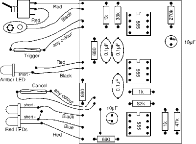
A magnet under the train operates reed switches positioned on the track. The trigger reed switch starts the sequence by switching on the amber light, a few seconds later the two red lights start to flash. When the train has passed the level crossing it operates the cancel reed switch which switches off the lights until the next train arrives.
There is a PCB pattern for this project, but if you don't have facilities to make PCBs you can build this project on stripboard instead. Please see the New Railway Modellers website for a stripboard layout and advice on making model lamps and barriers.
This project uses a 555 monostable circuit to switch on the amber LED for a few seconds. When this switches off it triggers a 555 bistable circuit which switches on a 555 astable circuit to flash the red LEDs.


Parts Required

>>resistors: 680 ×3, 1k ×3, 33k, 47k, 82k, 270k
>>capacitors: 0.1µF ×3, 10µF radial ×2
>>red LED (3mm best) ×2
amber* (or yellow) LED (3mm best)* some amber LEDs are too orange to look correct, yellow may be better
>>555 timer IC ×3
>>8-pin DIL socket for IC ×3
>>on/off switch
>>battery clip
>>reed switch ×2
>>miniature magnet - each locomotive needs one
>>printed circuit board (PCB) - pattern given below

PCB component layout


Track connections


The reed switches can be held in place between the rails with a small piece of blu tac.


Each locomotive will need a miniature magnet glued to its underside, test first with blu tac, then use superglue.


Circuit diagram


PCB copper track pattern


Stripboard layout

If you don't have facilities to make your own PCB you can build this project on stripboard. Please see the New Railway Modellers website for a stripboard layout as well as advice on making model lamps and barriers.


Model Railway Signal Project


A magnet under the train operates reed switches positioned on the track. The first reed switch changes the signal to red as the train passes, then further along the track a second reed switch changes the signal back to green ready for the next train. The isolated section of track just in front of the signal is switched off by the relay when the signal is red so a train will stop automatically at the red signal.


Parts Required

>>resistors: 1k ×2, 33k ×2
>>capacitors: 220µF
>>1N4001 diode
>>1N4148 diode
>>red LED (3mm best)
>>green LED (3mm best)
>>555 timer IC
>>8-pin DIL socket for IC
>>push-switch ×2
>>reed switch ×2
>>relay SPCO 12V coil
>>miniature magnet - each locomotive needs one
>>stripboard 11 rows × 24 holes


Stripboard layout


Track connections


Connect the reed switches to push-switches A and B (see the stripboard layout).


The switches can be held in place between the rails with a small piece of blu tac.


Connect the track wires to the COM and NC contacts of the relay.


When soldering to the track make sure you solder to the outside of the rail.


Each locomotive will need a miniature magnet glued to its underside - test first with blu tac, but superglue is probably best once you are sure it is in the correct position.


Note that railway signals have red at the bottom, unlike road traffic lights where red is at the top.


Circuit diagram


Light-sensitive Alarm Project


The circuit detects a sudden shadow falling on the light-sensor and sounds the bleeper when this happens. The circuit will not respond to gradual changes in brightness to avoid false alarms. The bleeper sounds for only a short time to prevent the battery running flat. Normal lighting can be used, but the circuit will work best if a beam of light is arranged to fall on the light-sensor. Breaking this beam will then cause the bleeper to sound. The light sensor is an LDR (light-dependant resistor), this has a low resistance in bright light and a high resistance in dim light.

The light-sensitivity of the circuit can be adjusted by varying the 100k preset.
The length of bleep can be varied from 0.5 to 10 seconds using the 1M preset.


Using the 7555 low-power timer ensures that the circuit draws very little current (about 0.5mA) except for the short times when the bleeper is sounding (this uses about 7mA). If the circuit is switched on continuously an alkaline PP3 9V battery should last about a month, but for longer life (about 6 months) you can use a pack of 6 AA alkaline batteries.


Download PDF version of this page


Parts Required

>>resistors: 10k, 47k, 1M ×3
>>presets: 100k, 1M
>>capacitors: 0.01µF, 0.1µF, 10µF 25V radial
>>transistor: BC108 (or equivalent)
>>7555 low-power timer IC
>>8-pin DIL socket for IC
>>LDR (light-dependant resistor) type ORP12
>>bleeper 9-12V
>>on/off switch
>>battery clip for 9V PP3
>>stripboard 12 rows × 25 holes


Stripboard Layout


Circuit diagram


Adjustable 1-10 Minute Timer Project


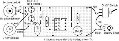
The circuit starts timing when switched on. The green LED lights to show that timing is in progress. When the time period is over the green LED turns off, the red LED turns on and the bleeper sounds.
The time period is set by adjusting the variable resistor. It can be adjusted from 1 to 10 minutes (approximately) with the parts shown in the diagram. You can mark the times on a scale drawn on the box.
Please note that the range of time periods is only approximate. With perfect components the maximum time period should be 4½ minutes, but this is typically extended to about 10 minutes because the 220µF timing capacitor slowly leaks charge. This is a problem with all electrolytic capacitors, but some leak more than others. In addition the actual value of electrolytic capacitors can vary by as much as ±30% of their rated value.


Download PDF version of this page


Parts Required

>>resistors: 470, 33k, 100k
>>variable resistor: 1M
>>capacitors: 0.1µF, 220µF 16V radial
>>LEDs: red, green
>>bleeper 9-12V
>>555 timer IC
>>8-pin DIL socket for IC
>>on/off switch
>>battery clip for 9V PP3
>>stripboard 10 rows × 22 holes


Stripboard Layout


Circuit diagram


Simple Electronic Lock Project


There are six (or more) push switches. To 'unlock' you must press all the correct ones at the same time, but not press any of the cancel switches. Pressing just one cancel switch will prevent the circuit unlocking. When the circuit unlocks it actually just turns on an LED for about one second, but it is intended to be adapted to turn on a relay which could be used to switch on another circuit.
Please Note: This circuit just turns on an LED for about one second when the correct switches are pressed. It does not actually lock or unlock anything!


Download PDF version of this page


Parts Required

>>resistors: 470, 100k ×2, 1M
>>capacitors: 0.1µF, 1µF 16V radial
>>red LED
>>555 timer IC
>>8-pin DIL socket for IC
>>on/off switch
>>push-switch ×6 (or more)

>>battery clip for 9V PP3
>>stripboard 12 rows × 25 holes


Stripboard Layout


Circuit diagram


Flashing LED Project


This project is designed as an introduction to soldering, identifying common components, using the resistor colour code and placing components correctly on stripboard. The LED flashes at about 3Hz (3 flashes per second). This project uses a 555 astable circuit.


Download PDF version of this page


Parts Required


>>resistors: 470, 1k, 220k
>>capacitor: 1µF 16V radial
>>red LED (or orange, yellow or green if you prefer!)
>>555 timer IC
>>8-pin IC holder (a 'DIL socket') for the 555 IC
>>battery clip for 9V PP3
>>stripboard: 6 rows × 21 holes


Instructions


Solder the 8-pin IC holder in the correct place on the stripboard.

Break the 4 tracks under the IC holder with a track cutter tool. You can allow extra holes if your piece of stripboard is large enough.


Use the resistor colour code to identify the resistors which are marked with coloured bands to show their value.


Insert and solder the resistors in the correct position, they can be put in either way round, but you must line them up correctly with the IC holder.


Identify the other parts, then solder them in the correct position and the right way round. To help you identify the parts please see our page on soldering.


Solder the 2 wire links in place around the IC holder, it is easier to use plastic-coated single-core wire. (The flexibility of stranded wire is not needed for connections like this and the strands can be difficult to push through the small hole).


Finally insert the 555 timer IC and connect a battery! For a circuit diagram of the 555 astable circuit used in this project please see the Stripboard page.


Quiz Project


This project can be used for a quiz with up to 4 contestants (or teams). Each contestant has a trigger push-switch and LED. When a trigger switch is pressed it lights the corresponding LED, sounds the bleeper and prevents the other trigger switches from working - therefore showing which contestant was the first to press their switch. A reset push-switch (operated by the quizmaster) cancels the bleeper and switches off the LED so the circuit is ready for the next question.
Take great care to arrange the parts correctly on the compact stripboard layout. The LEDs are shown mounted directly on the stripboard but you may prefer to mount them on a box using short wires. The trigger switches need long cables of about 2 metres so they can be held by, or placed near, the contestants.
The circuit consists of four 555 timer bistables which are triggered or reset when their inputs are low. Their reset inputs are connected together and operated by a single reset push-switch. The trigger switches are connected to the bistable trigger (pin 2) through a 0.1µF capacitor so that only the initial press triggers the bistable; continuing to hold the switch closed will have no effect. This is called edge triggering. Connecting the switch directly to the bistable would prevent the quizmaster from resetting the circuit until the trigger switch was released and trials showed that many contestants kept the switch pressed until asked to give their answer! When triggered the bistable output (pin 3) lights an LED and makes the 'trigger line' high - this prevents any other bistable being triggered and sounds the bleeper. A diode is used to link the output to the trigger line.


Download PDF version of this page


Parts Required


>>resistors: 470 ×4, 1k ×2, 10k ×8
>>capacitors: 0.1µF ×4, 1µF radial
>>diodes: 1N4148 ×4
>>LEDs: 1 each red, green, yellow and blue, all 5mm diameter
>>555 timer ICs (such as NE555) ×4
>>DIL sockets for ICs: 8-pin ×4
>>bleeper suitable for 9V
>>on/off switch
>>push switch ×5
>>battery clip for 9V PP3
>>2-core cable such as 'figure 8', about 8 metres
>>stripboard: 10 rows × 50 holes


Stripboard Layout


Circuit diagram