Valentine Heart Project


This project flashes 18 LEDs at three different rates and you can use these to create an eye-catching Valentine Heart. The circuit is kept simple (and low cost) by using the 4060B IC which is a counter and oscillator (clock) in one package. The circuit requires a 9V supply, such as a PP3 battery. It will not work with lower voltages and a higher voltage will destroy the LEDs.
The preset variable resistor can be used to adjust the oscillator frequency and this determines the flash rate of the LEDs. The IC limits the current to and from its outputs so the LEDs can be safely connected without resistors in series to limit the current. The stripboard part of the circuit is easy to build but the wiring for the LEDs needs care so detailed instructions are provided below.


Parts Required
>>resistors: 10k, 470k
>>preset: 47k (this could be 100k if necessary)
>>capacitor: 0.1µF
>>4060B IC
>>16-pin DIL socket for IC
>>LEDs × 18, 5mm diameter, red (or any mix of red, orange, yellow and green)
>>on/off switch
>>battery clip for 9V PP3
>>stripboard 13 rows × 18 holes


Stripboard Layout


Building the Circuit

Begin by soldering the components onto the stripboard as shown in the diagram above. Do not insert the 4060B IC at this stage.

Arranging the LEDs:

Cut out a suitable shape from stiff card (or similar material), such as the Valentine Heart template. Paint or colour the card at this stage if necessary.
Plan the layout of the 18 LEDs (suggested positions are marked on the template).
Drill 5mm holes for the LEDs - put the card on a piece of scrap wood to do this without damaging the card or the table.
Push LEDs into the holes, they should be a fairly tight fit and glue should not be necessary.
Label the LEDs D1 - D18 at random on the back of the card.


Circuit diagram


Heart-shaped Badge Project


The badge consists of eight LEDs arranged in the shape of a heart. One LED is lit at a time and this 'chases' round the shape. It would be easy to adapt this project to create other shapes with the eight LEDs. This project uses a 555 astable circuit to provide the clock pulses for the 4017 counter.

Parts Required

>>resistors: 2.2k, 47k, 270 ×8
>>capacitors: 0.1µF, 1µF 16V radial
>>red LEDs ×8
>>555 timer IC
>>4017 counter IC
>>DIL sockets for ICs: 8-pin, 16-pin
>>on/off switch
>>battery clip for 9V PP3
>>safety pin to attach badge
>>ribbon cable 9-way about 1 metre (to connect badge to main circuit)
>>stripboard: 16 rows × 19 holes for circuit, 10 rows × 9 holes for badge


Stripboard Layouts


Circuit diagram


Christmas Decoration Project


This project flashes 18 LEDs at three different rates and you can use these to create a Christmas decoration of your choice. The circuit is kept simple (and cheap!) by using the 4060B IC which is a counter and oscillator (clock) in one package. The circuit requires a 9V supply, such as a PP3 battery. It will not work with lower voltages and a higher voltage will destroy the LEDs.
The preset variable resistor can be used to adjust the oscillator frequency and this determines the flash rate of the LEDs. The IC limits the current to and from its outputs so the LEDs can be safely connected without resistors in series to limit the current. The stripboard part of the circuit is easy to build but the wiring for the LEDs needs care so detailed instructions are provided below.


Parts Required
>>resistors: 10k, 470k
>>preset: 47k (this could be 100k if necessary)
>>capacitor: 0.1µF
>>4060B IC
>>16-pin DIL socket for IC
>>LEDs × 18, 5mm diameter, any mix of colours: red, orange, amber, yellow or green
>>on/off switch
>>battery clip for 9V PP3
>>stripboard 13 rows × 18 holes

Stripboard Layout


Building the Circuit

Begin by soldering the components onto the stripboard as shown in the diagram above. Do not insert the 4060B IC at this stage.


Arranging the LEDs:

Cut out a suitable shape from stiff card (or similar material). Paint or colour the card at this stage if necessary.
Plan the layout of the 18 LEDs (suggested positions are marked on our template).
Drill 5mm holes for the LEDs - put the card on a piece of scrap wood to do this without damaging the card or the table.
Push LEDs into the holes, they should be a fairly tight fit and glue should not be necessary.
Label the LEDs D1 - D18 at random on the back of the card.


Model Lighthouse Project


This project was designed for a model lighthouse to flash a lamp in a simple sequence: two flashes of 2s with a short gap of 1s, followed by a longer gap of 5s before repeating the sequence.
The 555 timer is connected as an astable to provide clock pulses for the 4017 counter. The 4017 has ten outputs (Q0 to Q9) and each one becomes high ('on') in turn as the clock pulses are received. Outputs Q0, Q1, Q3 and Q4 are combined with diodes to produce the flash sequence. A transistor amplifies the current to power the lamp, or LED if you prefer (a 470 LED resistor is included on the stripboard layout). The 1M preset controls the time period (T) of the 555 astable from about 0.1s to 1.5s, for example set T = 1s.
For a different flash sequence connect the diodes to combine different 4017 outputs (Q0-Q9). If the full count from 0 to 9 is not required one of outputs can be connected to the reset input (pin 15). For example connecting Q8 (pin 9) to reset (pin 15) reduces the long gap at the end of the sequence to 3s (with T=1s).


Parts Required

>>resistors: 470, 2k2, 22k, 100k
>>capacitors: 0.1µF, 1µF 16V radial
>>diodes: 1N4148 ×4
>>transistor: BC108 (or equivalent)
>>1M preset, horizontal
>>6V 60mA MES lamp
>>MES lampholder
>>555 timer IC, such as NE555
>>4017 counter IC
>>DIL sockets for ICs: 8-pin, 16-pin
>>on/off switch
>>battery clip
>>9V battery box for 6 AA cells
>>stripboard: 19 rows × 21 holes


Stripboard Layout


Circuit diagram


Dice Project


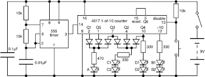
Press the push switch to 'throw' the dice: this makes the circuit rapidly cycle through the dice numbers so that an effectively random dice number is displayed by the LEDs when the push switch is released.
Drill seven 5mm holes in a dice pattern to mount the LEDs on a panel such as a plastic box lid or sheet of thin plywood. They should be a tight fit but a little glue can be applied from the underside if necessary.


The 555 astable circuit provides clock pulses at about 5kHz for the 4017 counter which has ten outputs (Q0 to Q9). Each output becomes high in turn as the clock pulses are received. Only six counts (Q0-Q5) are needed so Q6 is connected to reset. Appropriate outputs are combined with diodes to supply the LEDs: for example Q1, Q3 and Q5 are combined for LED A.
The dice sequence has been started at 2 so the ÷10 output can be used for LEDs B1 and B2, this saves diodes and simplifies the circuit. Pressing the push switch makes the disable input low so that counting occurs.


Parts Required


>>resistors: 330 ×3, 470, 10k ×3
>>capacitors: 0.01µF, 0.1µF
>>diodes: 1N4148 ×6
>>LEDs: red 5mm diameter ×7
>>555 timer IC, such as NE555
>>4017 counter IC
>>DIL sockets for ICs: 8-pin, 16-pin
>>on/off switch
>>push switch
>>battery clip for 9V PP3


>>stripboard: 20 rows × 22 holes


Stripboard Layout


Circuit diagram


Traffic Light Project


This project operates red, amber and green LEDs in the correct sequence for a single UK traffic light. The time taken for the complete red - red & amber - green - amber sequence can be varied from about 7s to about 2½ minutes by adjusting the 1M preset. Some amber LEDs emit light that is almost red so you may prefer to use a yellow LED.
The 555 astable circuit provides clock pulses for the 4017 counter which has ten outputs (Q0 to Q9). Each output becomes high in turn as the clock pulses are received. Appropriate outputs are combined with diodes to supply the amber and green LEDs. The red LED is connected to the ÷10 output which is high for the first 5 counts (Q0-Q4 high), this saves using 5 diodes for red and simplifies the circuit.


Parts Required

>>resistors: 470 ×3, 22k, 100k
>>capacitors: 0.1µF, 1µF 16V radial, 10µF 16V radial
>>diodes: 1N4148 ×6
>>LEDs: red, amber (or yellow), green
>>1M preset, horizontal
>>555 timer IC, such as NE555
>>4017 counter IC
>>DIL sockets for ICs: 8-pin, 16-pin
>>on/off switch
>>battery clip for 9V PP3
>>stripboard: 20 rows × 21 holes


Stripboard Layout


Circuit diagram


Dummy Alarm System


This Dummy Alarm project makes an LED flash briefly once every 5 seconds to imitate the indicator light of a real alarm. The circuit is designed to use very little current to prolong battery life so that it can be left on permanently. An on/off switch is not included, but could be added if you wish.
The 7555 timer IC used is a low power version of the standard 555 timer. A 'superbright' red LED is used because this provides a bright flash with a low current. The LED is off for most of the time so the average total current for the circuit is less than 0.2mA. With this very low current a set of 3 alkaline AA cells should last for several months, maybe as long as a year.
The circuit will work with a standard 555 timer IC (such as the popular NE555) but this will increase the average current to about 2mA and the battery life will be much shorter. You can use a greater supply voltage (15V maximum) for this circuit but the 1k resistor for the LED should be increased to keep the LED current low at about 3mA. For example to use a 9V PP3 battery change the 1k resistor to 3k3. Note that AA cells will last longer than a 9V PP3 battery.


Parts Required

>>resistors: 1k, 10k, 680k
>>capacitor: 10µF radial
>>LED: red superbright, 5mm diameter
>>7555 low power timer IC
>>8-pin DIL socket for IC
>>battery clip
>>4.5V battery box for 3 AA cells
>>stripboard: 8 rows × 16 holes


Stripboard Layout


Circuit diagram